Setup Arduino development kit
This documents presents an overview of the Arduino development kit provided by Hyper and the instructions to connect all of the components. The development kit includes an Arduino development board with an example source code for sensor integration and a Hyper Link WiFi device that can be connected to the Arduino development board to publish the data to the cloud deployment and allow local monitoring during development.
Components
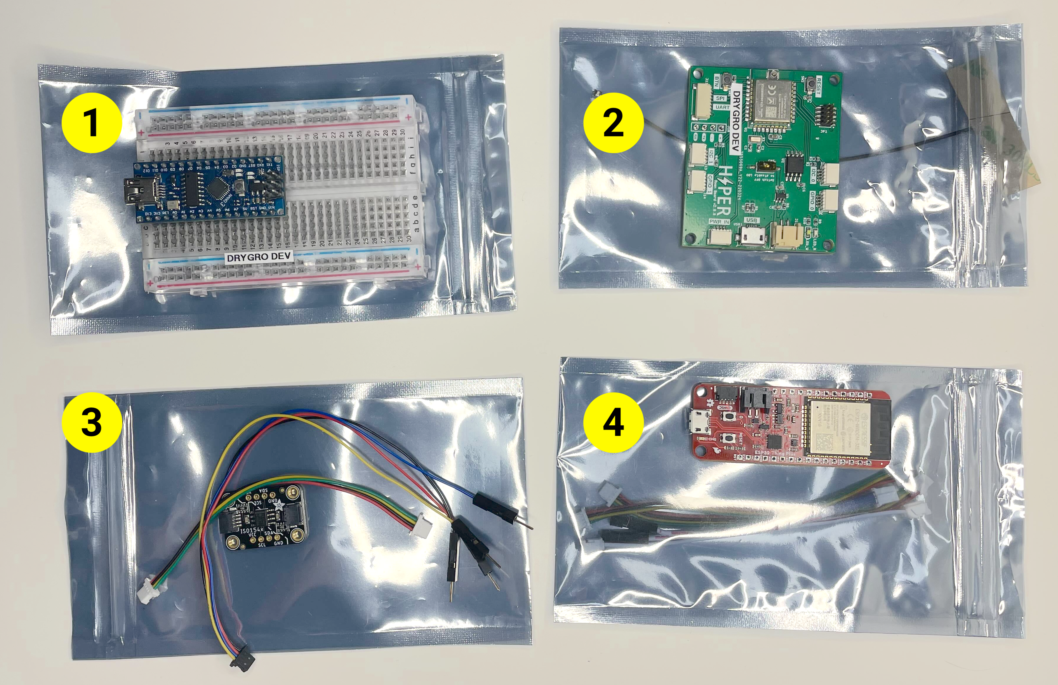
The development kit includes the following components and parts:
-
Arduino-compatible board - serves as an example external device programmed by users;
-
Hyper Link Thread device - a device that provides Thread connectivity and can be used in a production environment to connect the Arduino-compatible board to a Thread mesh network.
-
Bidirectional I2C isolator - an I2C isolator with two STEMMA QT/Qwiic connectors that should be used to connect the Hyper Link devices to the Arduino-compatible board.
-
Hyper Link WiFi device - a device that provides WiFi connectivity and can be used during development to monitor the values recorded by the Arduino-compatible board;
| The Hyper Link Thread device requires a Thread-compatible gateway device that creates the mesh network and forwards the data to Hyper’s cloud environment. The gateway device is not included in the development kit and is only required for production deployments. |
The sections below will provide an overview about individual components and explain how the kit can be assembled.
Arduino-compatible board and I2C isolator
The Arduino-compatible board included in the kit is meant to be a reference example of an external device to be integrated with the Hyper platform. The Arduino-compatible board is pre-configured as an external Hyper device with a number of sensor attributes.
The source code of the the Arduino project is available at https://github.com/hyper-systems/hyper-link-arduino.
You can use this device to test the integration, program it in a way that suits your use case to collect any sensor measurements or even trigger execution of commands.
| The device used in this example has the same pin layout and MCU as the "Arduino Nano" board. |
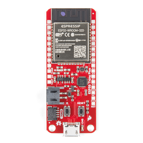
Hyper Link WiFi device
Use this device to connect the Arduino-compatible board provided in the kit to establish a WiFi connection and start collecting sensor readings. The collected data can be viewed locally in a web UI provided by the Hyper Link WiFi device itself and, in addition to that, will be published to a cloud deployment associated with your account.
For more information see the Configure Hyper Link WiFi device device page.
Hyper Link Thread device
Use this device to connect the Arduino-compatible board provided in the kit to establish a Thread connection with a Thread gateway device (such as Hyper Edge). Similar to the Hyper Link WiFi board, this device provides an I2C STEMMA QT/Qwiic connector.
Both Hyper Link Thread and Hyper Link WiFi devices implement the same data collection protocol allowing for seamless transition from WiFi to Thread connectivity.
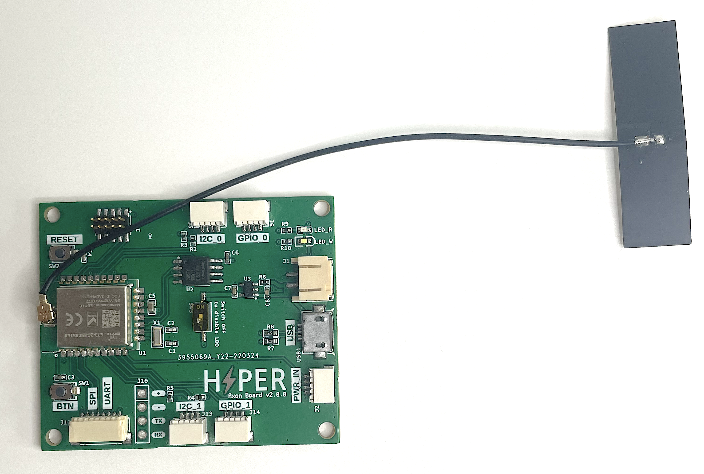
| The Hyper Link Thread device was originally called "Hyper Axon". Some development kits might included a board with the "Hyper Axon Board" label. |
For more information see the Hyper Link Thread device page.
Connect the kit
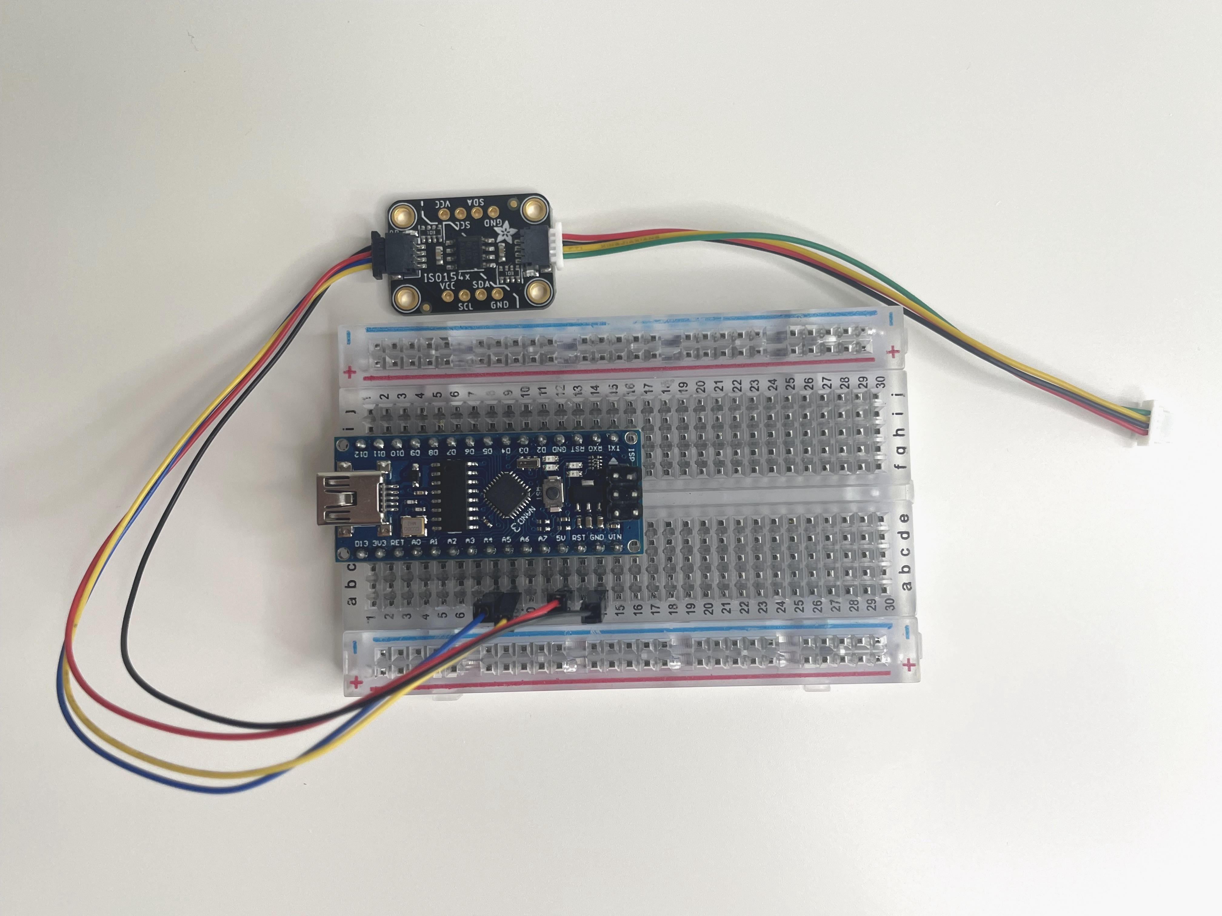
The figure below demonstrates all of the components connected and ready to use.
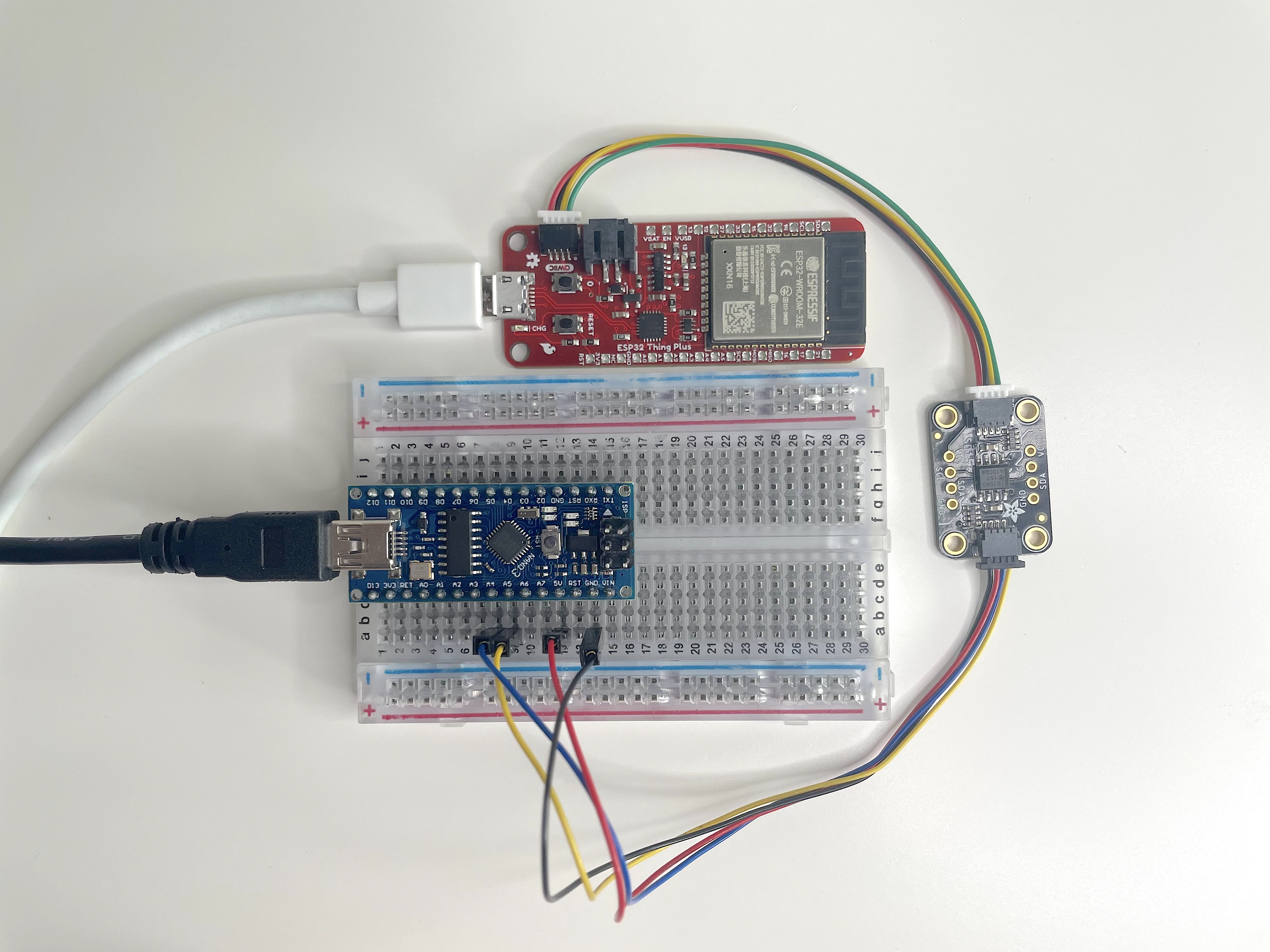
Here are the steps you can follow to fully recreate this setup:
-
Position the breadboard with the Arduino-compatible device as illustrated on the image.
-
Connect the pins of the I2C cable using the following mapping:
-
A4- SDA/Blue wire -
A5- SCL/Yellow wire -
5V- Red wire -
GND- Black wire
-
-
Connect the opposite end of the I2C cable with pins to the I2C isolator board and use an I2C cable with STEMMA QT/Qwiic connectors on both ends to connect the Hyper Link WiFi board (the red board on the image).
-
Connect the Arduino-compatible device to your computer using a mini USB cable.
-
Power on the Hyper Link WiFi device using a 5V micro USB connection. You can connect it to your computer or a secondary power source like a 5V battery or a charger.
Your setup should now look like Figure 5.
Setup the board in Arduino IDE
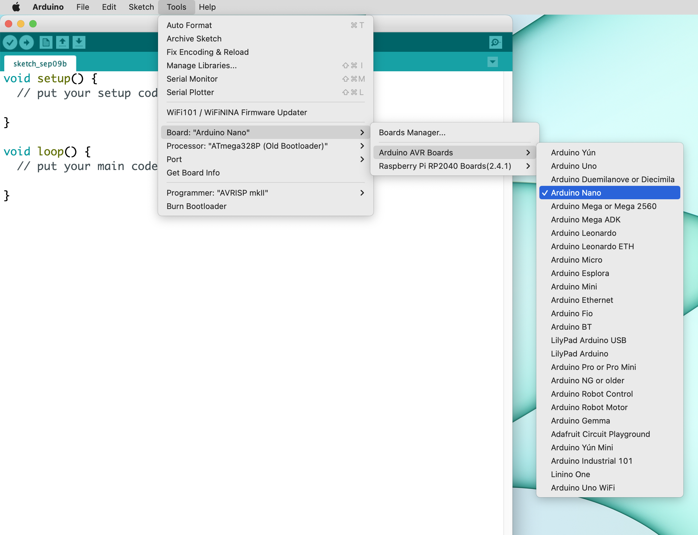
Once the Arduino-compatible device is connected to your computer, you can open Arduino IDE (version 1.18.x is recommended) and setup the environment.
You will need to select the "Arduino Nano" board, the "ATmega328P (Old Bootloader)" processor and a correct "Port" in the Tools menu. If you have both devices, the Hyper Link and the Arduino-compatible board, connected you will see two USB serial ports. You can temporarily disconnect the Link device to determine what port is associated with the Arduino-compatible device (normally it will look like /dev/cu.usbserial-130).
Congratulations you should now have a working kit ready to be programmed and tested.
Go to the Integrate the Hyper Arduino library page to learn how you can start recording sensor values.